
From SoC/SoH algorithms and balancing to module topologies and thermals to propagation control – practical, resilient, without marketing fog
Why the system decides – not the individual cell
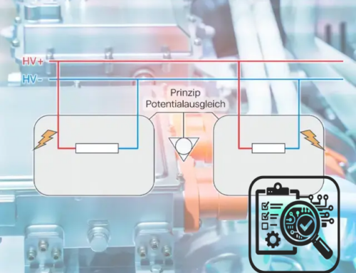
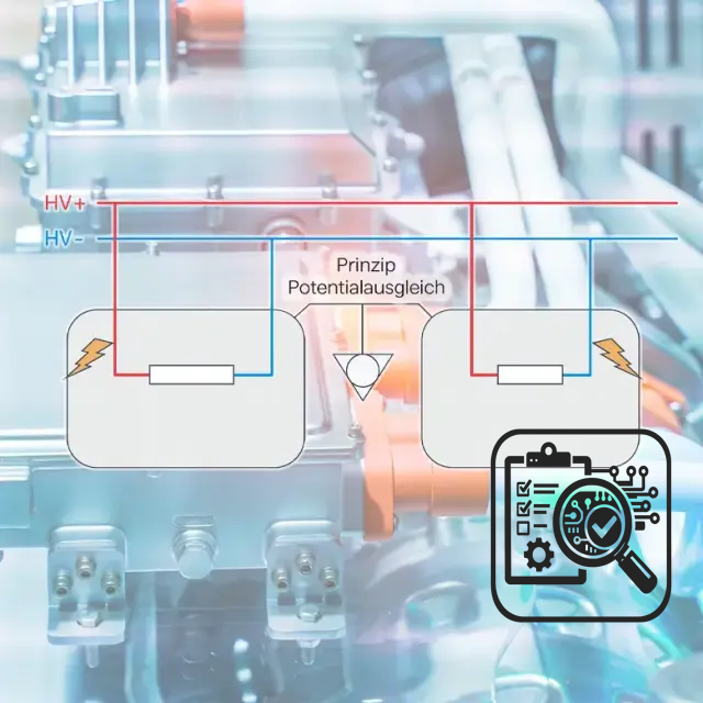
Performance, range, fast-charging capability, service life and safety are created in the battery system. Only through the proper interaction of the battery management system (BMS), electrical/thermal architecture, mechanical integration and monitoring/protection concepts can many cells become a reliable energy storage system for the vehicle, industrial plant or grid. Important in operation: The thresholds between low voltage (< 60 V) and low voltage or high voltage (≥ 60 V DC) require different qualifications and training – both for work on the system and for release and maintenance.
The following is a technically sound overview of BMS functionality, designs/topologies, system ageing and safety, tailored to the work of electrical engineers, master electricians and chief responsible electrical specialists (CRES).
BMS: The brain of the memory – measuring, deciding, protecting
Core tasks – without them there is no reliable performance
- Measurement & monitoring: cell voltages (each cell/group), string/pack voltage, currents (charging/discharging), temperatures (cell/module/coolant), insulation resistance to vehicle/system.
- Protection logic: limit values for overvoltage, undervoltage, overcurrent (peak/steady), overtemperature, undertemperature, insulation; time filters/debouncing; escalation paths from derating to safe shutdown.
- Balancing:
- Passive (resistance): robust, cost-effective, thermal to be considered.
- Active (capacity redistribution): reduces scattering better, more complex in hardware and control.
- Condition estimate:
- SoC (State of Charge): Coulomb counter + OCV mapping; in practice with observers (EKF/UKF/particle filter) and temperature compensation.
- SoH (State of Health): Derived from capacitance, impedance (DCIR/EIS proxies), efficiency and aging surrogates.
- SoF (State of Function): power-related limit values (instantaneous charging/discharging power) depending on T, SoC, SoH.
- Power path control: pre-charge/pre-charge sequences (RC time constants), contactors/pyro-fuses, DC link management.
- Thermal integration: control of pumps/fans/valves, heat pump coupling, preconditioning for fast charging and cold operation.
- Diagnostics & logging: Error classes, counter readings, event/data logger – basis for traceability and root cause analysis.
Architectures – centralized, modular, distributed
- Centralized: one controller + cell monitoring on one circuit board; suitable for small packs, short cables.
- Modular (master/slave): BMUs at module level, CMU/master coordinated; automotive standard, good scalability.
- Distributed (distributed sensing): Measurement ASICs close to cells, robustness against common mode interference, fewer cable harnesses.
Communication: CAN/CAN-FD, LIN, increasingly Ethernet backbone in large packs; galvanic isolation and EMC concept are mandatory.
Practical toolkit: A BMS is a protective device, measurement technology and predictor all in one. Without reliable sensors and properly validated models, there can be no reliable release or derating decisions.
Designs & system topologies: From module to pack architecture
Serial/parallel connection – more than simple mathematics
- S in series increases voltage, P in parallel reduces current per cell and internal resistance – influences power, losses, cooling requirement.
- Layout (e.g. SxPy) determines the number of strings/modules, backup concept, balancing granularity and fault tolerance in the event of cell/module failures.
Module concepts
- Single modules: identical cells, one BMU, integrated temperature sensors, integrated cooling channels if necessary.
- Smart modules: local computing power for balancing/diagnostics; reduces master load, increases interchangeability.
- Service strategy: access to plugs, venting, mechanical guidance – what seems trivial in CAD determines replacement times in the field.
Pack housing & cooling
- Housing: aluminum/steel profiles, extruded parts, composite materials; tightness class (IP protection), vent/exhaust air paths, EMC shielding.
- Cooling:
- Air: simple, cost-effective, limited power density.
- Liquid (plates/extrusion channels): high heat flow, homogeneous temperature, ready for fast charging.
- Direct refrigerant cooling: compact, very effective, higher integration requirements.
- Immersion cooling (dielectric): excellent homogeneity/propagation control, requires special media/material compatibility.
Electrics & protection
- HVIL (High Voltage Interlock Loop): Manipulation/disconnection point detection.
- Pre-charging resistor & contactors: controlled build-up of the DC link.
- Fuses/pyro-fuses: fast, selective disconnection in the event of fault energy.
- Insulation monitoring: continuous measurement against ground; limit value control dynamically adapted to humidity/temperature.
Practical tips: There is no such thing as the “best” design. Requirements → topology: installation space, performance, thermal, service, costs – and the desired fault tolerance in the event of degradation.
System ageing: Why packs age differently than cells in the data sheet
Cell-to-cell scattering becomes a system problem
Even small differences in capacitance/impedance lead to SoC drift within a string. Consequences: early derating, frequent use of balancing, uneven heat development. Active balancing reduces drift, but does not replace the need for homogeneous temperature.
Thermal gradients & edge cells
Edge cells see different boundary conditions (cooling, radiation, air gaps) – the warm zones age faster (SEI growth, electrolyte/CEI degradation), drive up impedance and shift performance limits. Design goal: minimize ΔT (over area and depth).
Operating strategy shapes service life
- SoC window: 10-90 % instead of 0-100 % brings noticeably more cycles; for stationary storage systems, possibly even more conservative – even better 15 % – 85 %. (Complete discharge would also be extremely damaging)
- Performance profiles: Fast charging only within a thermally conditioned window; cold + high C rates → risk of Li-plating (irreversible lithium losses, increasing DCIR) – keep cool is the key battery technology requirement.
- Calendar share: High lying SoC and temperature promote side reactions – mature strategies “park” packs defensively.
System signatures of ageing
- DCIR increase at pack level (not linear to the individual cell due to current distribution).
- Increase in balancing energy as a drift indicator.
- More frequent limit value events (temperature, cell voltage) → Derating becomes a “permanent state”.
Practical rule of thumb: Pack ageing is dispersion + thermal + strategy. If you have ΔT, SoC window and fast-charging window under control, you can shift the service life kink significantly to the right.
System security: prevention, detection, limitation
Sources of error & triggers
- Electrical: overcharging, internal/external short circuit, insulation fault.
- Thermal: local hot spots due to contact problems/high impedance, cooling failure, heat input from outside.
- Mechanical: Crash/vibration, crushing, penetration of foreign bodies; with pouch: swelling + lack of compression.
- Chemical: electrolyte/gas release, transition metal dissolution (inside the cell), moisture ingress.
System-side protective measures
- BMS side: multi-stage limit value monitoring, derating before switch-off, logic for fail-operational/fall-back, diagnosis of sensor errors (plausibility check/multi-channel capability).
- Electrical protective elements: pre-charging circuit, fast pyro-disconnection, selective fuses at module/string level, HVIL.
- Thermal measures:
- Homogeneous cooling (keep ΔT small),
- Thermal barriers (mica, aerogel, intumescent layers),
- Targeted gas/pressure paths (venting channels, defined blow-off directions),
- Detection of early indicators (atypical temperature rises, DCIR jumps, gas/particle sensors).
- Mechanics/containment: pressure-relieved housing, crash frames, defined load paths; tightness against moisture/media (IP protection).
Mastering propagation
Thermal runaway propagation is the system risk. Levers:
Practical toolkit: Security follows the chain Prevent → Detect → Limit. No single component is enough – only the combination works.
EMC, insulation & leakage issues – the silent showstoppers
- EMC/EMI: DC/DC converter, pump/compressor, inverter switching processes – without proper ground routing, filters and shielding, there is a risk of incorrect measurements in the BMS (ghost faults) and faulty shutdowns.
- Insulation resistance: ages due to moisture, dirt, coolant leaks; measurement under varying conditions (temperature/humidity) necessary.
- Coolant compatibility: Conductive or chemically aggressive media are system-critical – sensor technology + material compatibility are not a “nice-to-have”.
- Tightness: Realistically check IP protection classes (pressure changes, climatic cycles). Moisture is a fire and ageing accelerator.
Operating strategy & BMS algorithms – performance without regrets
- Dynamic SoC window: outside temperature, ageing status, load profile → adaptive window improves service life and availability.
- Power enable (SoF): temperature/impedance/SoC-dependent; soft limits prevent hard shutdowns and voltage dips.
- Preconditioning: Preheating before fast charging (especially at < 10 °C), if necessary cold operation with reduced C-rates.
- Recuperation: limit at high SoC/low temperature (risk of plating).
- Balancing policy: “Early & often” reduces drift; active strategies save energy, but are more regulation-intensive.
Measurement and diagnostic tools in system operation
- DCIR tracking (periodic pulse/current jumps, possible on-board): Early indicator for contact problems, ageing, thermal issues.
- EIS-related methods (low-frequency DCR, model-based observers): for fleet operation and predictive maintenance.
- dQ/dV analysis (off-board, laboratory): Deep insight into ageing mechanisms (LLI/LAM).
- Thermography & ΔT metrics in the pack: visualize cooling quality, identify edge cells.
Practical takeaways (compact & practicable)
- Think BMS first: Protection, measurement, SoC/SoH/SoF are the levers for performance and service life.
- Align topology to requirements: S/P interconnection, module size, cooling concept, service access – all system compromises.
- Keep ΔT small: Thermal homogeneity is lifetime protection; fast charging only thermally conditioned.
- Actively manage drift: Balancing strategy + dispersion control prevent “early derating”.
- Safety in layers: BMS limits, electrical separation, barriers, gas/pressure paths, propagation proofs.
- Below 60 V ≠ (ev) high voltage: voltage limits define qualifications, measuring/protective equipment and approval processes – different training requirements are mandatory. In the world of battery systems, there is also a 120 V limit, but many safety aspects are standardized for static battery systems starting at 60 V.
Conclusion: System excellence is the true battery technology
Those who master battery systems orchestrate cells, BMS, thermals, electrics, mechanics and operation into a coherent whole. The major levers lie in
PS: Our recommendation: Our free(REALLY free, even WITHOUT having to provide an email address!) paper “6 things you need to know in advance about the high-voltage qualification of your employees” is available here (click).


Leave A Comment