
Why manufacturing determines performance, costs and safety
Whether energy density, fast-charging capability, service life or safety window – the course is set in battery production. Formulation, process control and quality assurance determine whether a cell performs stably in the field or ends in complaints and follow-up costs. This technical article from Battery Technology bundles the central steps from electrode slurry, separator, electrolyte and cell assembly to formation and end-of-line testing – compact, practical and without marketing fog.
Cathode production: Energy density is (also) a process
1) Powder mix & slurry
The cathode mixture combines active material (e.g. NMC or LFP), conductive additive(s) and binder (typically PVDF in NMP). The decisive factors are
- Dispersion: break up agglomerates without damaging particles. Too high shear forces destroy surfaces; too low create islands with local over/under conduction.
- Viscosity & rheology: Slurry must be stable (no sediment) but easy to coat. Temperature control influences viscosity and wetting.
- Moisture: Water < ppm range. Residual moisture promotes hydrolysis (e.g. LiPF₆ → HF) in later process steps.
2) Coating & drying
- Coat weight (g/m²) and layer thickness determine capacity per area (area loading).
- Drying curve: Solvent removal without skin formation (“skinning”) – otherwise porosity gradients occur which impair ion transport and cyclability.
- Solvent recovery: NMP extraction and recovery (EHS, costs) are part of OPEX optimization.
3) Calender & pore structure
- Density & porosity: Calender pressure, roll temperature and speed define the compact density.
- Trade-off: Higher density increases volumetric energy density, but reduces porosity and increases tortuosity → poorer fast-charging capability and temperature balance.
- Goal: Application-dependent optimum instead of maximum compaction.
4) Cutting & edge quality
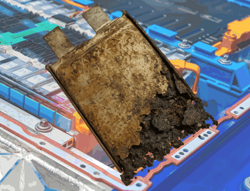
Burrs/burrs at the selvedge are short-circuit risks. Cutting parameters, blade condition and web-guiding ensure dimensional accuracy without fiber breakage.
Practice takeaways (cathode):
- Validate slurry window (shear profile, temperature, mixing time).
- Lay the drying profile so that the porosity remains homogeneous.
- Specify density/porosity in relation to load profile and cooling (not “one value for all”).
Anode production: SEI fitness starts with the coating
1) Binder systems & water process
Graphite anodes are increasingly water-based (SBR/CMC), which simplifies explosion protection and exhaust air purification. CMC molecular weight and SBR content control elasticity, cracking tendency and adhesion.
2) Lead additives & surface chemistry
The type and proportion of conductive soot (often 1-3 %) influence electronic percolation. Too much soot reduces energy density; too little increases IR drop.
3) Coating, drying, calendering
As with cathodes – with the addition that surface properties and residual moisture strongly influence SEI formation in the formation. The aim is a thin, elastic SEI with low internal resistance and low gas formation.
4) Silicon components
Si composites increase capacity, but require elastic binder concepts, adapted calendering and formation (elongations in the cycle). Without these process windows → rapid fade, gassing, bloating.
Practice takeaways (anode):
- Clean qualification of water-based processes (drying, residual moisture, wetting).
- Aim for SEI-compliant surfaces (roughness, chemistry) instead of just “thick = good”.
- For Si composites: early material-process co-development.
Separator: Invisible safety belt with influence on performance
Polyolefin separators (PE/PP, mono- or trilayer) are standard. Important points:
- Thickness & porosity: Thin increases energy density, but reduces puncture resistance. Pore distribution must be homogeneous.
- Shutdown function: PE melts earlier (pores close), PP carries mechanics – only protects with moderate temperature rise kinetics.
- Surface treatment: wettability (electrolyte absorption), if necessary ceramic coatings for temperature stability and mechanical robustness.
- Format dependency: Large pouch/prismatic cells sometimes require thicker films/coatings; cylindricity and winding tension influence wrinkle freedom and short-circuit risk.
Practice takeaways (separator):
- Link separator selection consistently to format, charging power and safety concept.
- wetting time and electrolyte uptake as quality-relevant key figures.
Electrolyte: Conductivity, stability and additives as levers
1) Solvent blend
Combinations of cyclic and linear carbonates balance conductivity, viscosity and temperature window. EC promotes a dense SEI on graphite, PC is critical for graphite (co-intercalation).
2) Conductive salt & humidity
LiPF₆ is the de facto industry standard despite its susceptibility to hydrolysis. Humidity control (< 20 ppm, depending on specification) is non-negotiable: HF formation attacks LE salt, electrode surfaces and SEI.
3) Additive (SEI/CEI design)
- VC/FEC for robust SEI, lower impedance increase.
- (ev) high voltage additives/film formers (CEI) for > 4.2 V systems.
- Mn stabilization with LMO components via suitable additive packages.
Practice takeaways (electrolyte):
- Select additives according to the application (ev) high voltage, fast charging, low temp).
- Moisture management as an integrated system (material → drying room → assembly → filling).
Cell assembly: from electrode strip to closed system
1) Cell structure & formats
- Wrap (“jelly roll”) vs. stack: Wrap dominates cylindrical/prismatic; stacked electrodes (stack) are common in pouch.
- Tab design & current paths: Low-resistance discharge, clean welding spots (ultrasonic/laser welding) and defined thermal paths are mandatory.
2) Drying & drying room
Before installation: Electrodrying and conditioning in the drying room (Dew Point typ. ≤ -40 °C) → Minimize residual moisture of the active layer.
3) Electrolyte filling & wetting
- Pressure/vacuum sequences control pore wetting.
- Soak time and, if necessary, tempering in order to completely saturate even dense electrodes (high compaction).
- Degassing for pouch/prismatics after initial cycles to remove any gases formed.
4) Seal & housing
- Pouch: sealing parameters (temperature, time, pressure) → helium leak rate.
- Prismatic/cylindrical: Test geometric tolerances and lid/bottom closures for pressure changes and temperature cycles.
Practice takeaways (assembly):
- Qualify wetting window per electrode/separator (weight absorption, EIS).
- Validate welding parameters regularly in coupon tests (tensile strength, resistance).
- Early helium leak test saves late scrap costs.
Formation & Aging: finalizing chemistry
1) Formation – the “birth” of the cell
Multi-stage charge/discharge protocols at a controlled temperature form the SEI (anode) and CEI (cathode). Key objectives: low internal resistance, low gas formation, stable lithium balance.
- Current density & C-rate: Too aggressive → thick, brittle SEI; too gentle → cycle time suffers, OPEX increases.
- Temperature window: too cold → slow SEI kinetics; too warm → side reactions, gassing.
2) Aging (“rest”) & final conditioning
After formation: resting phase (temperature controlled) to complete diffusion processes, stabilize SEI and degas impurities. Pouch cells are usually degassed again and finally sealed.
Practice takeaways (formation):
- Develop material/design-specific protocols (graphite vs. Si anode, LFP vs. (ev) high voltage cathodes).
- Link capacity binning strategy with formation (selective binning reduces dispersion in the pack).
Quality assurance: Measure before it gets expensive
Inline controls
- Coat weight & thickness: Beta/X-ray measuring systems, optical inspection for defects (pinholes, binder lakes).
- Moisture content: Karl Fischer/Inline sensors on electrodes and winding room air.
- Calender log: Continuously monitor pressure/temperature/gap; establish correlation to EIS/OCV drift.
End-of-Line (EoL)
- OCV & DCIR: Early indicator for short circuits/contact problems.
- Capacity & efficiency: Reference cycle(s) under standard conditions.
- Tightness (He test), leakage currents, insulation test.
- Statistical process control (SPC): Attribute and variable maps; root cause analysis (Ishikawa, DoE) anchor.
Practice takeaways (QA):
- Live SPC not “for the audits”, but as a management tool.
- Actively establish correlation process signal ↔ cell characteristic value (e.g. drying profile ↔ EIS low frequency).
- Ensure traceability up to reel/batch level.
Factory planning: from the drying room to energy management
Layout & Media
- Drying rooms are energy hotspots – zoning, airlock design and heat recovery save OPEX.
- Cleanly separate the NMP circuit (cathode) and waste water (anode, water-based).
- Scaling: Logistics and buffers dominate from MWh lines (cycle synchronization between coating ↔ calender ↔ assembly).
Occupational safety & explosion protection
- Solvent rooms: explosion protection zones, extraction volume flows, LEL monitoring.
- Avoid dust explosions (powder handling, ATEX concept, earthing).
Thinking quality + costs together
- First-pass yield beats “later sorting”.
- OEE (Availability, Performance, Quality) to focus on bottleneck steps – typically coating/drying, calendering and forming.
Common misconceptions – briefly debunked
- “More compression = better”: Not without load profile and cooling concept. Too dense = diffusion limitation, heat problems.
- “The thinnest separator is always optimal”: No. Mechanics and safety define a lower material limit.
- “Formation can save everything”: Formation optimizes chemistry – it does not compensate for structural production errors.
- “Additives are plug-and-play”: additive packages are material-specific tools; incorrect combinations impair service life.
Conclusion
Battery production is system engineering. Electrode formulations, coating/drying, calender windows, separator selection, electrolyte chemistry, cell assembly and formation are all interlinked. Those who synchronize these levers properly will achieve the target triangle of
PS: Our recommendation: Our free(REALLY free, even WITHOUT having to provide an email address!) paper “6 things you need to know in advance about the high-voltage qualification of your employees” is available here (click).


Leave A Comment