Measurement practice according to UN-ECE R100 (<0.1 Ω), typical fault patterns and why clean equipotential bonding stabilizes insulation monitoring (ISO monitor/IMD)
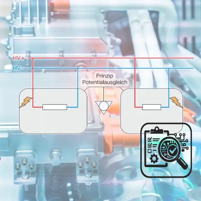
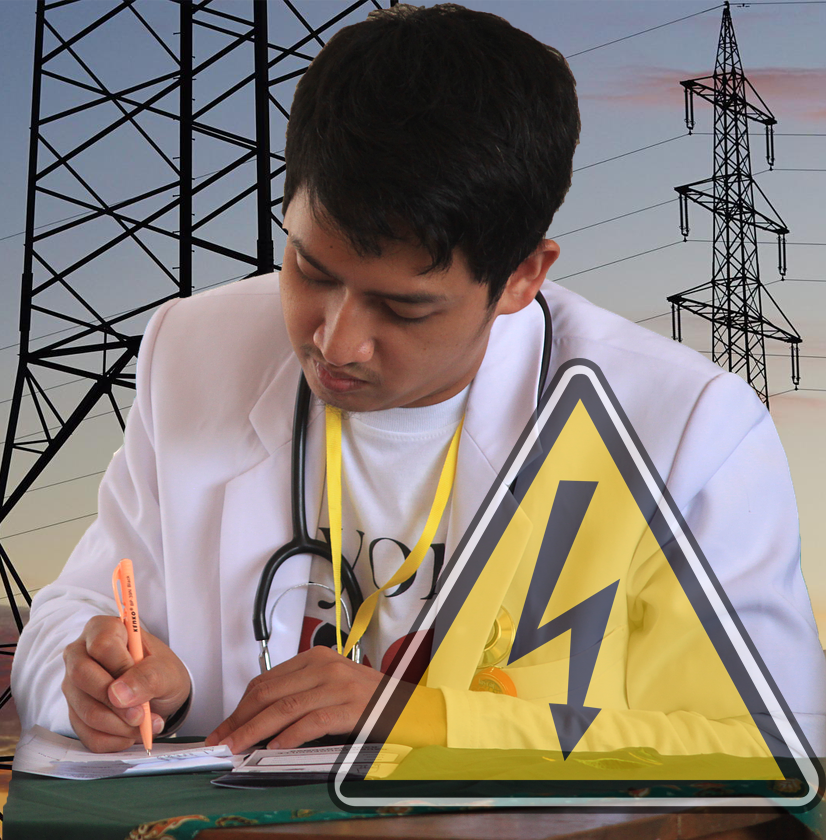
Equipotential bonding sounds like a compulsory program, but it is a central safety and quality feature in the (ev) high voltage system: it ensures that touchable conductive parts (e.g. housings, shields, body structures) are brought to a defined reference potential. This reduces dangerous contact voltages, stabilizes EMC-relevant return paths – and creates the basis for reliable diagnostic functions in the vehicle.
Why this is so critical in practice
In an HV (ev) vehicle, ground is not just a thick conductor; it is a system of contact points, screw connections, shield supports, transitions via paint/layers and potential corrosion. Even small contact resistances can:
-
falsify measurements,
-
Allow error images to “wander”,
-
and trigger unpleasant questions during audits (“Where is the reproducible testing and documentation?”).
Normatively, the topic is typically addressed via requirements for the low-resistance connection of touchable conductive parts (in practice often assessed with limit values in the range < 0.1 Ω in the context of UN-ECE R100 – without claiming detailed quotations here).
The often overlooked point: equipotential bonding and ISO monitors
The ISO monitor (insulation monitoring device or IMD) detects insulation faults by evaluating the insulation resistance of the HV (ev) system to the vehicle body/chassis. This is where potential equalization becomes a “quality factor”:
-
Stable reference: A clean potential equalization creates a defined, low-impedance reference system. This makes measuring conditions more reproducible.
-
More robust fault detection: Poor or slightly variable connections can cause the reference potential to fluctuate. This can lead to unclear symptoms: delayed detection, seemingly intermittent warnings or measured values that are difficult to interpret.
-
Better fault localization: If the bonding structure is consistent, insulation faults can be localized more systematically (instead of chasing ghosts behind contact problems).
In short: The ISO monitor does not measure in a vacuum, it measures against a reference system. And this reference system stands and falls with the equipotential bonding.
Checklist: Check in 7 steps
-
Clearly define measuring points (assembly to chassis/cover).
-
Prepare contact points (coatings, paint, oxide, corrosion).
-
Select a suitable measuring method (typically: four-wire with Kelvin terminals).
-
Define measuring conditions (contact pressure, measuring current, repetitions).
-
Evaluate results (limit value + R-test for outliers).
-
Document deviations with cause logic (not just “n. i. O.”).
-
File proof in an auditable format (device, calibration status, serial numbers).
Mini table: Method → Risk → Countermeasure
| Measurement method | Typical risk | Countermeasure |
|---|---|---|
| Two-wire | Falsify line/contact resistances | Use four-wire/Kelvin |
| Unclear measuring points | Not reproducible | Measuring point plan + photos |
| “Take a quick measurement” | Random values due to contact quality | Defined preparation + repetitions |
🎓 Conclusion:
Good equipotential bonding is not just safety technology, but a quality feature: it improves the validity of tests, strengthens audit capability and supports the reliable detection of insulation faults by the ISO monitor. No wonder that measuring equipotential bonding is a standard part of every high-quality (ev ) high voltage training course.
Equipotential bonding thus fulfills central safety tasks in the (ev) high voltage vehicle and is therefore so important in high voltage training courses. PS: Our recommendation: Our free(REALLY free, even WITHOUT having to provide an email address!) paper “6 things you need to know in advance about the high-voltage qualification of your employees” is available here (click).
Short FAQ (for at the end of the blog article)
1) What is equipotential bonding in (ev) high voltage systems?
A low-resistance connection of touchable conductive parts (e.g. housing, shields, body/chassis) so that they have a defined reference potential and no dangerous potential differences arise.
2) Why is the value < 0.1 Ω often mentioned?
In practice, the low-resistance bonding connection is often assessed in the context of UN-ECE R100 with limit values in the range < 0.1 Ω (the specific design depends on the system and test concept).
3) Why is a four-wire/Kelvin measurement useful?
Because it largely eliminates line and transition influences of the measuring lines. With very low resistances, the two-wire measurement quickly delivers incorrect values that are too high.
4) What are the typical causes of poor readings?
Coatings/paint, oxide/corrosion, unsuitable contacting, incorrect measuring point (e.g. “too far away” from the relevant bonding), lack of reproducibility in the setup.
5) What does equipotential bonding have to do with the ISO monitor (IMD)?
The ISO monitor evaluates the insulation status against a reference system (vehicle body/chassis). A clean equipotential bonding stabilizes this reference potential and thus improves the robustness and interpretability of the insulation monitoring.
6) What must be included in an auditable test report?
At least: defined measuring points, date, measuring device/serial number, calibration status, measuring method (e.g. Kelvin), conditions (contact preparation), result, evaluation and, if applicable, re-test/reason for deviation.


Leave A Comment